Fuel Oil System Piping Diagram
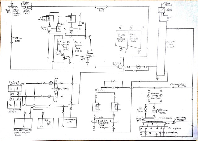
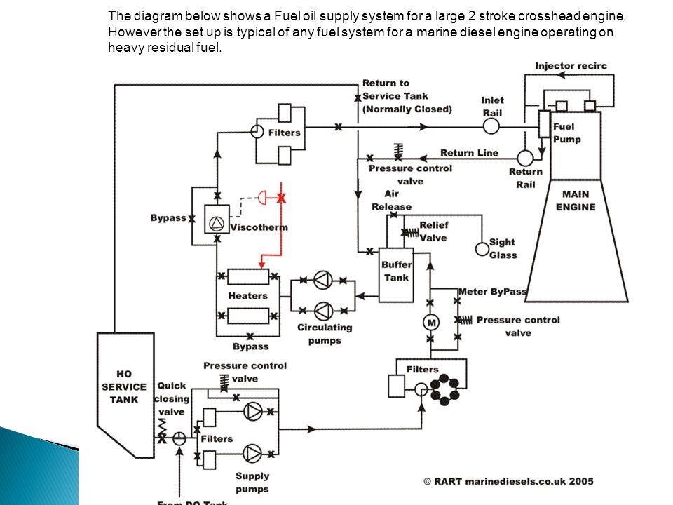
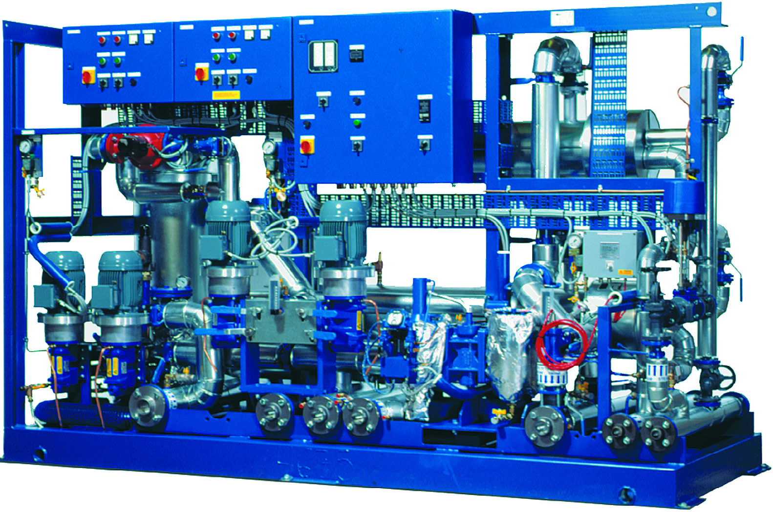
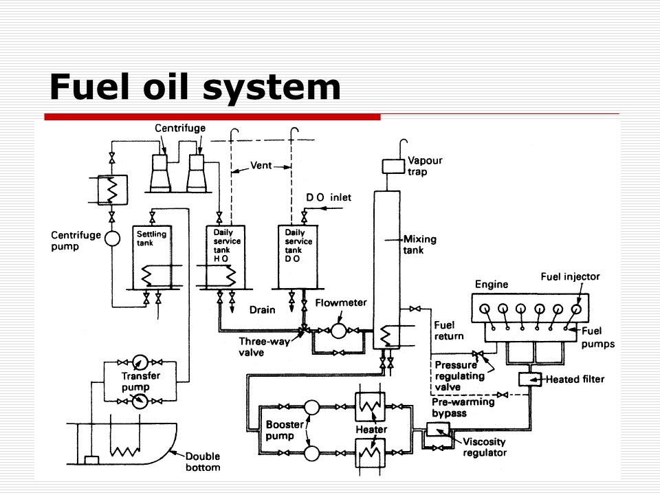
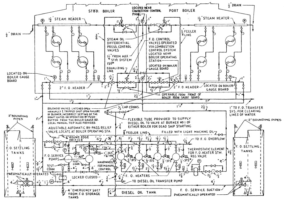
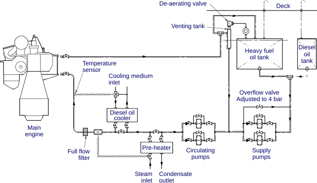
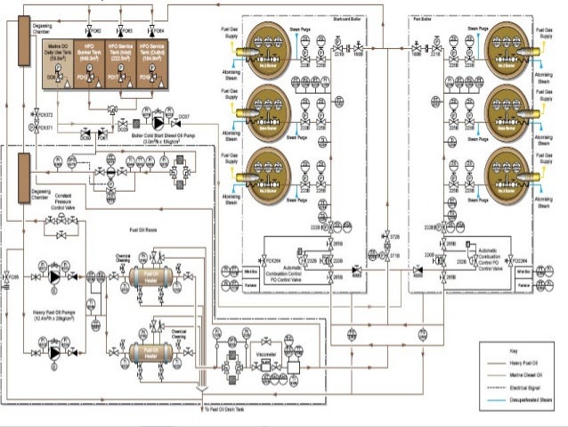
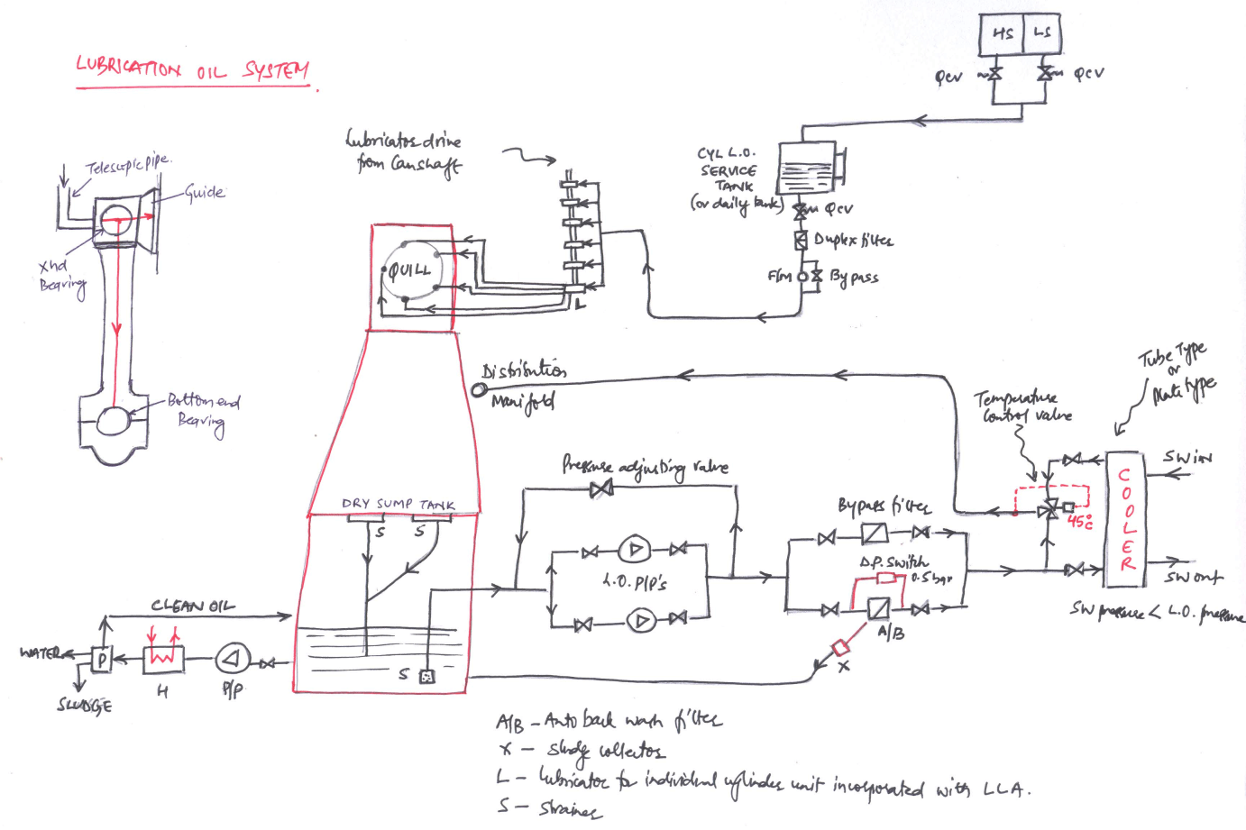
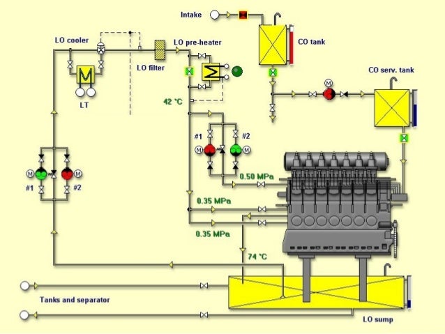
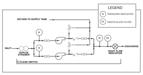
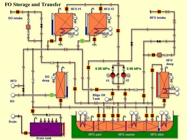
Fuel oil system piping diagram. Marine Fuel Oil Transfer System includes various piping systems provided for bunkering storage transfer offloading and treatment of fuel oils. Do not provide cross connections between grades. A system designer should be aware of a couple of key points when in-volved with boiler fuel oil systems.
Heating system oil burner by gravity flow. Applies to MFC Series Models. For cleaning of heavy fuel oils HFO the two stage process is commonly.
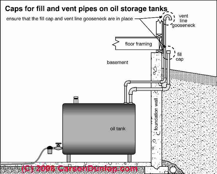
Return piping shall connect to the top of the fuel oil tank. Fuel systems a minimum viscosity of 14 cSt at 38C 100F is required at the engine transfer pump to properly lubricate fuel system components. Piping is so arranged that the pumps can transfer fuel between storage tanks and then to the deck connections for offloading.
The fuel oil day tank is located with the fuel oil storage tank in a separate room located at a building level above the diesel room. MFC 3000 MFC 4000 MFC 5000 MFC 6000 MFC 8000 MFC 10000 Gas Train. At the starboard side deck hose connection and using.
The most common causes of water in tanks are. Kerosene type fuels have lower energy content than diesel fuels and therefore will produce less peak power output andor will require more fuel volume to do an equivalent amount of work. C For short runs provide a line slope of at least 02 percent.
2 fuel oil NFPA Classification. Copper Tube 2 Fuel Oil 1. Class 4 ffi date e 2 12-2-96 sca-e no.
Provide a separate piping system for each grade of fuel to be handled. Refer to this cheat sheet for important considerations when designing a fuel oil system.
11 06 retired exeptic date cate cate civil elec.
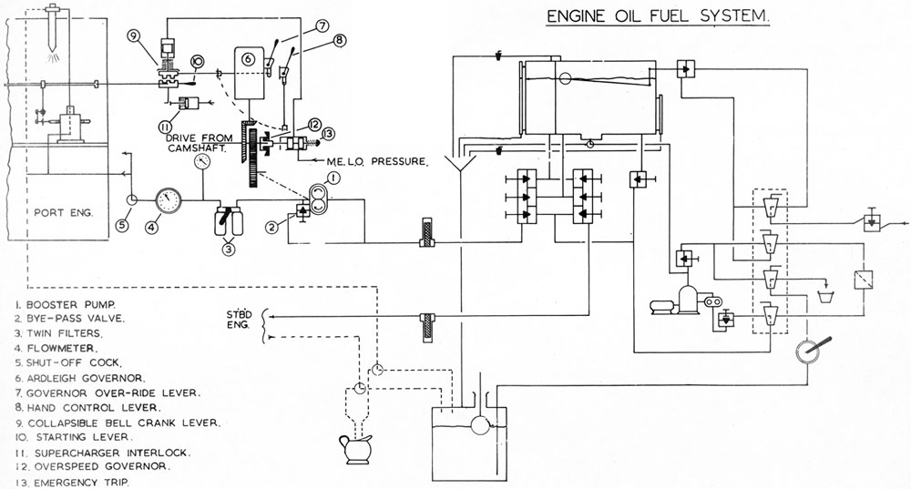
The fuel oil is pumped into the tug. This section shall not apply to inside or above-ground fuel oil tanks. I Fuel tank ii Fuel filter iii Sediment bowl iv Fuel lift pump v Carburettor vi Fuel pipes vii Inlet manifold In some spark ignition engine the fuel tank is placed above the level of the carburettor. 2 This pump can typically handle a low suction pressure of 15Hg without difficulty but a high suc-. Valves shall not be installed on return piping. Approximately 7 gph100 kW rating. FUEL OIL LINE DIAGRAM AND EXPLANATION IN SHIP. Applies to MFC Series Models. Provide a separate piping system for each grade of fuel to be handled.
For cleaning of heavy fuel oils HFO the two stage process is commonly. S 1514 pipe sch. Range day tank is filled by using the rotary hand pump. S 1516 1514 151. Measure total tube length horizontal and vertical from the end of the line in the tank to the connection at the oil pump. 11 06 retired exeptic date cate cate civil elec. Remove all sharp rocks and debris from the trench bottom before bedding material is installed.










Post a Comment for "Fuel Oil System Piping Diagram"